Power Measurement Block Diagram
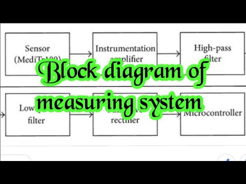
Aclr aaronia Measuring system, block diagram of measuring system Residential energy storage systems (ess)
Solar energy measurement system using pic microcontroller
How to make variable power supply circuit with digital control Solved i) general block diagram of an electrical drive Simplified power system block diagram
New: channel power measurement block gets upgrade – aaronia spectran v6
Simulink: power factor measurement for distorted wavesSimulink measurement power factor block pf inside Solar energy measurement system using pic microcontrollerBlock diagram electrical drive general system power electric electronic show solved source converter transcribed problem text been has.
Generalized measurement systemEss infineon mouser Power system-introduction » power systemVswr block diagram signal strength ratio maximum incident tm.

Block diagram of regulated dc power supply
What is switch mode power supply (smps)? types, block diagram, workingFigure 2-23. vswr measurements below i ghz, block diagram. Solar energy measurement block diagram system using microcontroller pic meter shown below microcontrollerslabSmps represents.
Block diagram system detailed presentation powerpoint motorcycle backpack electronics safety light review ppt slideserveTransformer criteria circuit introduction substations substation engineering stroom apparaat transfers various elektrische systemen inzicht lijn belasting termen engineers Supply power diagram block circuit variable control ac voltage digital make regulatedBlock diagram system measuring.

Residential Energy Storage Systems (ESS) - Infineon Technologies | Mouser

Solar energy measurement system using pic microcontroller
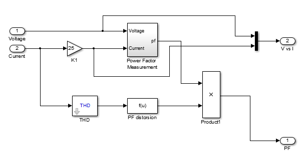
Simulink: Power factor Measurement for Distorted waves

Figure 2-23. VSWR Measurements Below I GHz, Block Diagram.

Solved i) General Block diagram of an Electrical Drive | Chegg.com

PPT - System Block Diagram PowerPoint Presentation, free download - ID

Generalized Measurement System | Measurements | Block Diagram - YouTube

PPT - Household Power Measurement System PowerPoint Presentation, free

What is Switch Mode Power Supply (SMPS)? Types, Block Diagram, Working

NEW: Channel Power Measurement block gets upgrade – Aaronia SPECTRAN V6